6 Guidelines and Mistakes to Avoid When Drawing a Data Flow Diagram

Maybe DFDs don’t look too complicated, but experience proves otherwise. So, it is not so easy to that easy to use data flow diagram. First of all, you need to have the appropriate names for processing and data flows. This means that you need to think carefully about how to follow all the rules when making a diagram.
It is important that it has the appropriate characteristics of the business process itself, because only then will your diagram be accurate. You must always be aware of the potential problems caused by common mistakes. These errors are an integral part of the process when you first try to create a DFD. There are several common types of errors, but you can easily overcome them with our tips.
1. Elements
Before you start working, you must fully understand how the process works, that is, gain insight into the entire system. After you adopt this information, you can add other content that includes much more information about the process. This refers to additional layers in the DFD that should be kept to a minimum. Standard data flow diagram symbols are used to represent different parts of the system. While one symbol is used for an external entity, the other is a minor zap rocs. Several symbols are used to create DFD.
There are several ways to add symbols. For example, you can drag a symbol into your workspace. You can also add a symbol to the library and imprint it on the page. Once you’ve done that, adding the next symbol works by selecting the desired symbol and clicking “add right”. Always use quick shortcuts if you want to get the job done as soon as possible. When you want to rearrange a symbol, just click on it and drag it to a new location. The chart will automatically adjust to the new structure, which means you don’t have to worry about drawing by hand. This website can give you even more info on data flow diagram components.
2. Steps in creating DFDs
Opt for a specific data flow diagram template. Then, name it. You will do this by clicking on Blank ERD & Data Flow. After the screen pops up, you can enter a chart name and your DFD will appear in the upper left corner of the screen. You can now add an external entity to start the process. Not only will you find plenty of shapes and symbols here, but you can also add different images to the diagram.
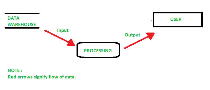
You can hover over each shape to understand what they represent. For example, these are process, data warehouses, external entity, etc. You need an nail entity to start the process, but so do the others. You will drag it to the workspace and type the name of the external entity. Next, add the process to the DFD, as well as the data store. Finally, keep adding items.
3. Physical and logical data flow diagrams

You will also need to make sure that your physical or logical DFD is more appropriate for your needs. If you are not sure which one you need, don’t worry because the difference is very obvious. While logical data flow diagrams focus on what happens in a particular flow of information, DFD involves business activity and all employees should have a good understanding of these diagrams. Logical data flow diagram is determined by software, hardware, etc. We must note that physical and logical diagrams can describe the same flow of information. Think carefully before you make a decision, because you may need both.
4. Data flow diagram levels
You can also categorize data flow diagrams by level. For example, start from the most basic, and start from level 0. As you climb up, DFDs become more complex. Before you start creating, think about the levels and decide at what level your diagram will be. The basic level gives you a wide view, it is easy to digest and you will have the opportunity to see very few details. This level actually implies the process node as well as its connections with external elements. When you step to the next level, you will still have an overview, but also more details. An individual process node is decomposed into subprocesses.
With the new processes come additional data streams as well as data warehouses for the purpose of connectivity. The next level breaks down the processes into more detailed subprocesses. Level 3 is significantly increased complexity. From the first to the third level, it was not difficult to understand the process, but here the process becomes much more complex. This means that the path to pseudo code after the second level is less and less understandable. However, these are the main processes within the system and each process is broken down into further processes.
5. Data flow in the wrong direction

Don’t forget this important detail. If you forget to turn on a data flow or set the arrow in the wrong direction, it will affect the whole process. Primarily we mean the loss of connection between data stores and entities. So always look at the diagram up to several times, because that way you will be sure that you have not left out any object or data flow. Remember that the data flow is described by a noun.
6. Equalization of DFDs and flow charts
Although this error is a little harder to identify, many have experience with this. So when building a diagram of this you should know that DFDs are not flow charts. While flow charts show only essential processing steps, DFDs will not display unnamed data flow. Don’t forget the differences between them. Otherwise you will have a bad experience with flow charts.
Conclusion:
If you want to succeed in creating a data flow diagram, consider all the processing steps as well as potential errors. It is important to remember all the characteristics and interdependent processes. Since the focus is on the flow of information, it is very important where the data comes from, where it moves and how it is stored.